| |
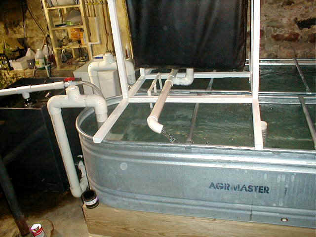
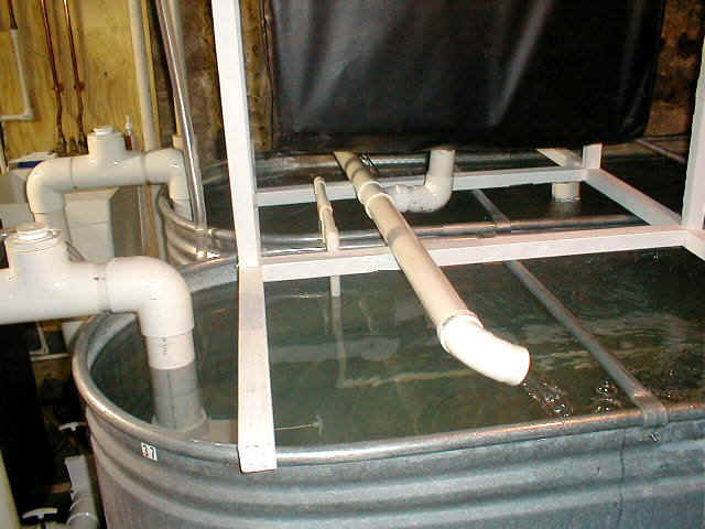
Photograph 1 shows most of the entire system, including the two tanks to the right, the clarifier to the left, the siphon system connecting the tanks to the Clarifier, and the biological filter mounted above the left end of the tanks.
Photograph 1
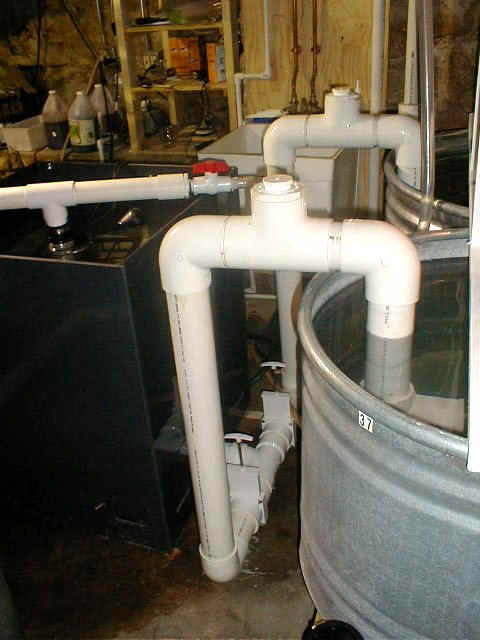
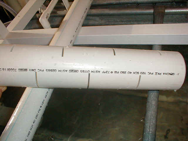
Water flows from the tanks into the PVC siphon system starting in the center of each tank. It is siphoned from the tank through three inch PVC down to the bottom of the Clarifier as shown in Photograph 2.
Photograph 2
Notice that at the bottom of the Clarifier (on the left) is a three inch "tee" with "gate valves" on each side, a valve for each of the two tanks siphon tubes. More about that latter.
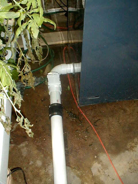
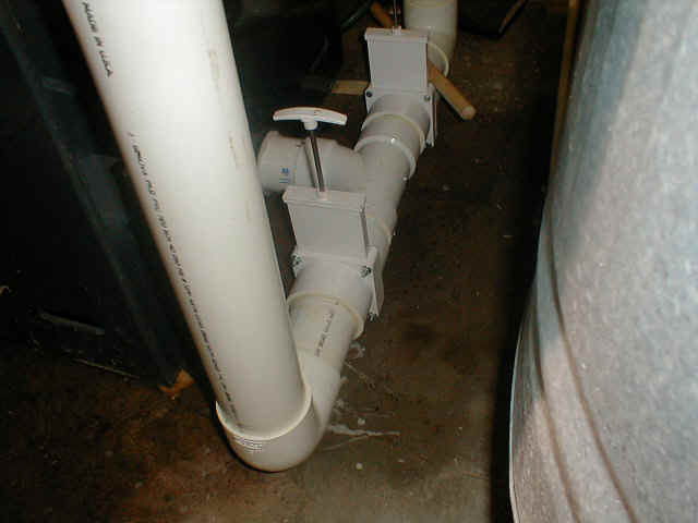
Once the water flows into the bottom of the Clarifier it encounters a series of "baffles" which stop the turbulence of the in-flowing water. This allows solid materials to settle to the bottom of the Clarifier. Periodically, the two gate valves on the intake side of the Clarifier are closed and a gate valve shown in Photograph 3 is opened to drain the entire clarifier, dispelling all accumulated waste into a sewage drain in the basement floor. Notice the rubber collar just down stream of the gate valve. This allows the three inch PVC drain tuning to be removed and stored away when not actually cleaning the Clarifier.
Photograph 3
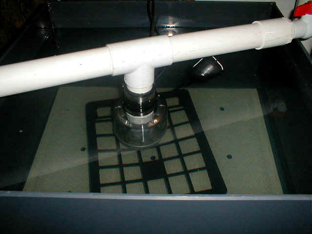
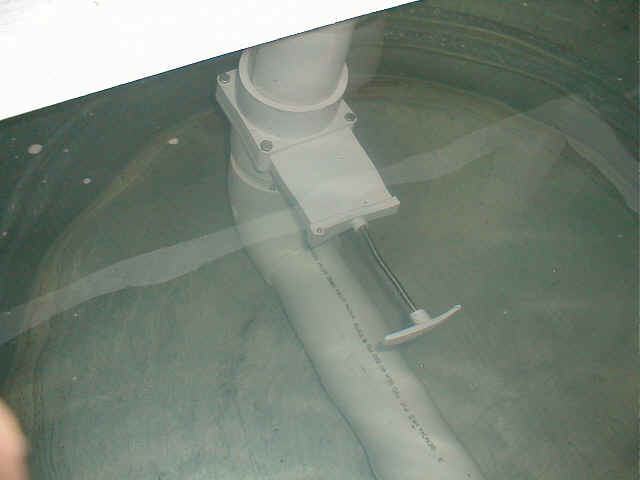
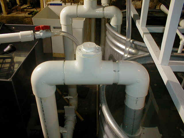
Because of the siphon action between the two tanks and the Clarifier, the water level in all three containers always remains equal. Water is circulated through the system by means of a submergible pump located under the water level in the top half of the Clarifier as shown in Photograph 4.
Photograph 4
The pump is setting on an inverted plastic "milk crate" which has been cut to a depth of four inches. This allows the PVC attached to the pump's output to just clear the top of the Clarifier. The PVC shown in Photograph 4 has two outputs preceded by a valve on each side. The valve (upper right hand corner) on the right allows water to flow into one and one half inch clear tubing which leads to the top of the biological filter (more on that in a moment). The valve to the left (not shown) leads to a garden hose fitting which allows the pump to be used to pump water from any part of the system when needed.
Photograph 5 shows the biological filter suspended above the tanks. Water, along with air flows through the biological filter where bacteria consume rotting dissolved material along with dissolved feces, producing nitrates which flow out of the filter and back into the two tanks.
Photograph 5
The biological filter is extremely important but at the same time very simple. The black rubber "bag" shown at the top of Photograph 5 contains plastic "milk crates" filled with PVC shavings from a lathe. These shavings have extremely sharp edges, and it is on these edges that the beneficial bacteria live and do their work of converting waste into nitrates. The entire contents of the "black bag" is shown in Photographs 6 and 7.
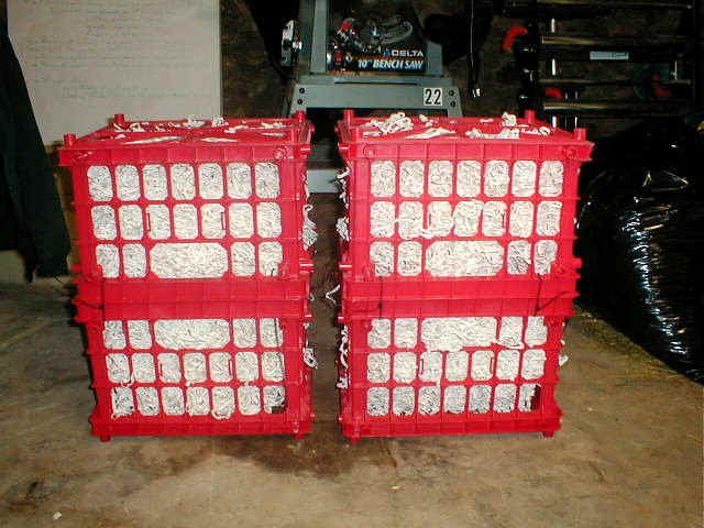
Photograph 6
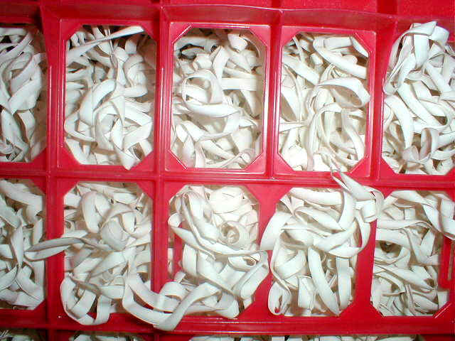
Photograph 7 ( close up )
Also shown in Photographs 1 and 5, just to the left of the water outlet from the biological filter you can see a 1/2 inch PVC pipe which carries air from a compressor down into the bottom of each tank, then along the bottom. The bottom section is drilled every four inches with a 1/16 inch hole, where air escapes, bubbling to the top and providing oxygen to the water.
More on the siphon system.
The siphon system is critical for the flow of water in this system. For those who have used any sort of siphon system, you can imagine the difficulty of starting a siphon flow through a rigid system of PVC pipe. This system's siphon is started as follows:
Both fish tanks are filled with water, while the Clarifier is empty. There is a pair of "gate" valves for each of the tanks; for a single tank, one inside the tank below the water level and another just before entering the "tee" at the bottom of the Clarifier. These valves are shown in Photographs 8 and 9.
Photograph 8
Photograph 9
In addition, at the top of the "loop", is a fitting which has a threaded "plug" at the very top. See Photograph 10.
Photograph 10
To start the siphon:
1. Remove the "plug" at the top of the loop.
2. Open the gate valve inside the tank, allowing the water level in the PVC pipe on the
tank side to rise to the tank's water level.
3. Close both the gate valve inside the tank and the one outside the tank.
4. Using a water hose, or funnel, fill the 3 inch PVC pipe between the two valves through
the "hole" where the plug was removed.
5. Once completely full, wrap the threads of the threaded "plug" with Teflon
tape and securely screw into the threaded hole at the top of the loop.
6. Open the gate valve inside the tank, then open the outside gate valve.
7. Water will immediately begin filling the Clarifier from the fish tank until the water
level in both Clarifier and tank are equal.
The above description speaks in terms of a single tank, but actually the siphons for BOTH tanks should be started simultaneously so that the strong water flow from the two tanks into an empty Clarifier will "sweep away" any trapped air bubbles. It should be emphasized that the entire siphon system which is exposed to the air must be absolutely air tight. Therefore, when assembling this part of the system, use an abundant amount of PVC cement and then use the cement on the OUTSIDE of all the connections and allow to cure before using.
More on the water Intake System.
Water inside the tank enters the siphon system in one of two ways. The normal setup is shown in Photograph 11.
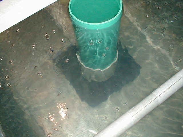
Photograph 11
The 3 inch PVC siphon pipe shown at the upper left of the image connects to the square black device on the bottom of the tank which has an attached white collar. Inside the large white collar the PVC pipe attaches to a 90 degree "ell" which is pointing up. The green stand pipe is to prevent water from above the collar from entering the siphon system. Below the collar is an opening to the black structure, which is two pieces of Plexiglas separated by about 3/8 inch. Water from the bottom of the tank enters the siphon system through this opening, drawing debris from the bottom of the tank. This is the normal configuration once the fish are large enough such that they can't be drawn through this opening.
For young, small fish another system is used as shown in Photograph 12.
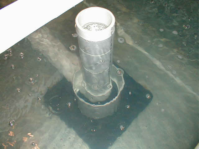
Photograph 12
Here we see a section of 3 inch PVC connected directly to the "ell" inside the collar. This section of PVC has 1/16 inch slits cut on opposing sides every 2 inches. Photograph 13 shows a clearer view of this section.
Photograph 13
This setup draws water from the entire depth of the tank water and is too small for young fish to be sucked into the siphon system.
Operation.
Once the system is started, there is very little maintenance. Every month or so the pump should be turned off and all gate valves closed on the intake side of the Clarifier. The drain PVC should be connected to the rubber collar on the drain side of the Clarifier and run to a drain point. The output side gate valve is then opened and the Clarifier emptied. The pump can be removed along with the screen upon which it sits and the inside of the Clarifier cleaned with a water hose. Once cleaned, the outlet gate valve is closed, and the screen and pump replaced inside the Clarifier. The gate valves inside the thanks are then opened. Last open the two outside gate valves simultaneously. This will cause the water level in the tanks to decrease some, so water should be added to bring the water level back to normal. It's also necessary, if not growing plants in the tanks (which would remove the nitrates), to periodically drain the fish tanks by about one third (just open all the gate valves until the water level has decreased by a third).
The biological filter requires no maintenance.
This page was produced by Ron Darby.